Guide for CAD2SHAPE Users
Creating Shapefiles for the E-LOI Portal
CAD2Shape is not a GIS or CAD application extension, but a stand alone desktop tool that can convert CAD (.dxf and .dwg) files into Esri shapefiles. It is extremely important that the CAD file you are trying to convert is properly formed prior to conversion. Please see the section on "CAD Workflow" for more information on CAD creation requirements.
Note: It is recommended that you download a copy of the Divisions LOI userdefs.udf file for use as a template for this software. Please be advised that the values of this attributes table template must be changed prior to first use with information relevant to your firm.
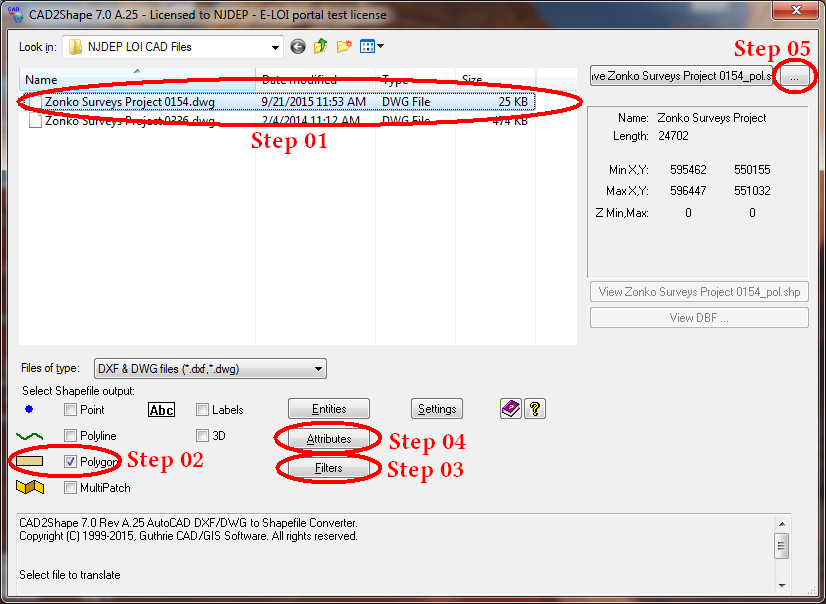
Step 1: When opening CAD2Shape, it will display a windows explorer type screen in the upper left part of the window. You must use this functionality to navigate to the appropriate folder on your desktop/network then choose (click on) the .dxf or .dwg file you wish to convert.
Step 2: From the "Select Shapefile Output" options (lower left) choose "Polygon". (Please note that the CAD file layers you wish to convert must already exist as polygons in CAD or they will not convert properly.)
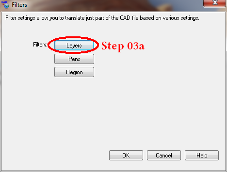
Step 3: Click on the "Filters" button to open the filters window.
FIGURE 1
The "Filters"Window
Step 3a: When you open the filters window, you must click on the "Layers" button to open the layers window.
FIGURE 2
The "CAD Layers to Translate" window
The layers window will show you all of the available layers within the CAD file you selected in "Step 1"
Step 03b1: Since all of the layers in your CAD file are checked by default, use the "Clear All" button to uncheck all of the layers.
Step 03b2: Check all of the layers you wish to export. Depending on the type of LOI you will be applying for, these will be one or more of the following: Site, Footprint, Wetlands and/or Transition Area. It is VERY important that, for your own sake, you label these layers clearly in CAD so that it is easy to pick out the layers you will need to export.
Step 03b3: When exporting multiple layers, it is important that you check the box "Output a separate shapefile for each selected layer".
Step 03b4: The template provided by the Department for the attributes table will require a minor change to be made for each shapefile so that they can be distinguished from one another. Please check the "Prompt for user data for each shapefile" checkbox and when the file is exported you will be prompted to make the appropriate change. Don't worry, this is explained a bit later in this tutorial.
FIGURE 3
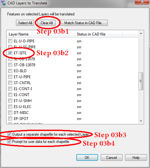
Click OK on this window, then OK again on the "Layers" window. This will take you back to the main CAD2Shape window.
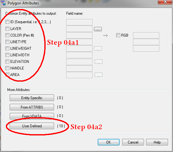
The "Polygon Attributes" window
Step 04: Click on the "Attributes" button shown in Figure 1 above. This will bring up the "Polygon Attributes" window.
Step 04a1: Make sure all of the "Common Entity attributes to output" checkboxes are unchecked.
Step 04a2: Click on the "User Defined" button. This will launch the"User Defined Attributes" window.
FIGURE 4
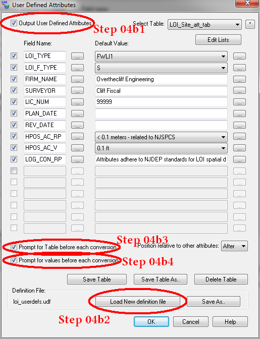
The "User Defined Attributes" window
Note: If you haven't done so already, download the LOI_userdefs.udf file for use as a template. This template will define the attributes for your shapefile. Shapefiles which do not have these template values, or which have fewer or more attributes than that in the template will not pass the portal validation tests.
Step 04b1: Check the "Output User Defined Attributes" checkbox.
Step 04b2: Click on the "Load New Definition button" and using the explorer window that pops up, navigate to where you have stored the .udf file you downloaded from the DEP (or the one you have modified from the DEP template and tailored to your firm) and click "Open" to load it.
Step 04b3: Check the "Prompt for Table before each conversion" checkbox.
Step 04b4: Check the "Prompt for values before each conversion" checkbox.
Close this window by clicking on the OK button. The Polygon Attributes table window will still be open. Close it as well by clicking on the OK button on that window.
FIGURE 5
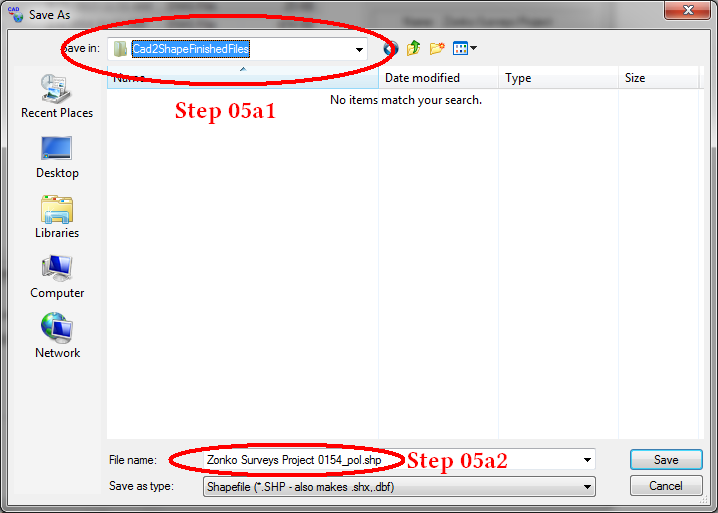
The "Save As" window
Step 5: As marked in Figure 1, click on "save as" icon ![]() which will bring up the "Save As" window.
which will bring up the "Save As" window.
Step 05a1: Navigate to where you wish to save your created shapefiles. (You may wish to have separate folders for each of your E-LOI projects where you also store the attachments you will be uploading to the portal. Whatever workflow works best for you and your organization.)
Step 05a2: Create a name for your shape file. It automatically defaults to the name used for your CAD file, but you can change this if you wish.
Click on the "Save" button. Once you do this, the conversion process begins and it will bring up the "Select User Attributes Table" window.
FIGURE 6
The "Select User Attributes Table" window
Step 06: Because the "Prompt for Table before each conversion" checkbox was checked, the "Select User Attributes Table" window will appear for each layer which is being converted, allowing you to modify the table attributes if necessary. Check that the CAD layer matches the selected table in the drop down menu. For example, if you are converting the "Site" layer, the matching table should be the "LOI_Site_att_tab" (LOI Site Attributes Table). Click ok if the correct table is listed.
In addition to the "LOI_Site_att_tab" table for exporting site layers to site shapefiles, you would use the "LOI_Footprint_att_tab" table for "Footprint" shapefile conversions, the "LOI_Wetlands_att_tab" table for wetland shapefile conversions and the "LOI_Transition_att_tab" table for wetland transition area shapefile conversions.
The "Enter User Attribute Values" window
Please Note: The Divisions LOI userdefs.udf file contains placeholder data only! The values of this attributes table template must be changed prior to first use with information relevant to your firm.
Step 07: On the "Enter User Attribute Values" window you will see the attributes in your modified template table. While some of these fields can be pre-populated with data from your firm, some values will be project specific.
Detailed information on the attribute tables can be found on the "LOI Shapefile Feature Attribute Table Structure and Attribute Descriptions" webpage.
The screen below is what you will see after following "Step 8" and loading the DEP template. You cannot and should not change the Field Names, since these field names are used as part of the validation in the DEP portal. You can however, change any of the field values that are not drop down lists by entering in new data in the field, so you can change the values for "FIRM_NAME", "SURVEYOR", "LIC_NUMBER", "PLAN_DATE", "REV_DATE" and "LOG_CON_RP".
You can also, if necessary, change the table for the values of the "HPOS_AC_RP", "HPOS_AC_V" fields by clicking on the "..." button to the right of the value field.
Once you have tailored the values to your firm, you can save your custom attributes table by clicking on the "Save As" button at the bottom of the screen next to the "Load New definition file" button.
As pictured below, there are four (4) different tables for exporting different CAD layers into shapefiles available in the "Select Table" drop down menu located at the top right of the window. For the "Site" shapefile, you would use the "LOI_Site_att_tab" (LOI Site Attributes Table). This table has one extra field than the others, the "LOI_TYPE" field. In this field you would chose as a value the type of LOI for which you are applying. The codes are as follows:
FWLI1: Presence Absence LOI
FWLI2: Footprint of Disturbance LOI
FWLI3: Delineation LOI
FWLI4: Verification LOI
If you have any questions about what each of these types of LOI's are, please go to the Freshwater Wetlands Webpage and click on the "Wetland Delineations" tab.
In addition to the "LOI_Site_att_tab" table for exporting site layers to site shapefiles, for the "Footprint" shapefile, you would use "LOI_Footprint_att_tab" table. For the "Wetlands" shapefile, you would use the "LOI_Wetlands_att_tab" table. Lastly, for the Wetlands Transition Area shapefile, you would use the "LOI_Transition_att_tab" table. The screen below shows what the "LOI_Site_att_tab" table looks like, which includes all 10 field types. The only difference between these three tables is the value for the "LOI_F_TYPE" field.
User Defined Attributes Table for Site Shapefiles
Below is an example of what the screen looks like choosing the "LOI_Footprint_att_tab" table in the "Select Table" dropdown menu. You will note that the "LOI_Type" field is grayed out. This field is only used for the "Site" shapefile. The only other change is that the value for the "LOI_F_TYPE" field has changed to "F" for "Footprint". The only difference between the "LOI_Footprint_att_tab" and the "LOI_Wetlands_att_tab" and "LOI_Transition_att_tab" tables is the value of the "LOI_F_TYPE" field. ("F" for footprint, "W" for wetlands, "T" for transition area.)
User Defined Attributes Table for Footprint, Wetland & Transition
Area Shapefiles,
Footprint Table Pictured Here